1.Appearance of Qilin battery pack overview
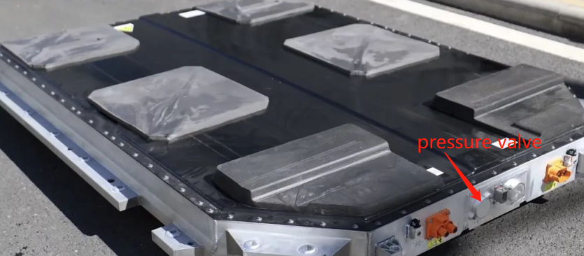
Let’s take a look at the appearance of the battery, which is not much different from the conventional design. There are 6 pieces of thick cushioning foam on the battery pack cover, and two pressure relief valves are installed on the front end. You can also see the rear end 4 pressure relief valves are set, so a total of 6 pressure relief valves are set in the entire battery pack.
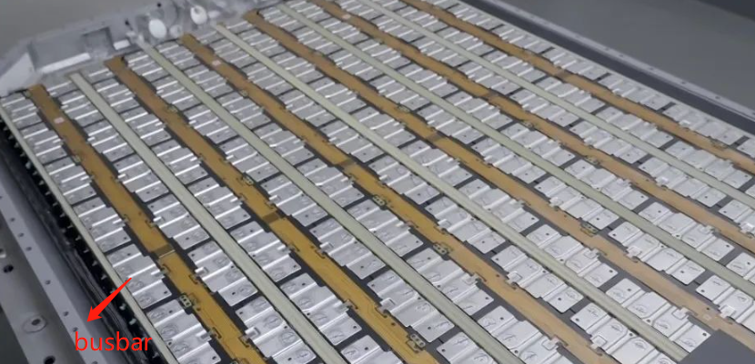
2.Busbar, BDU layout inside Qilin battery
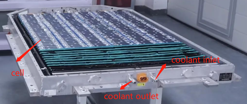
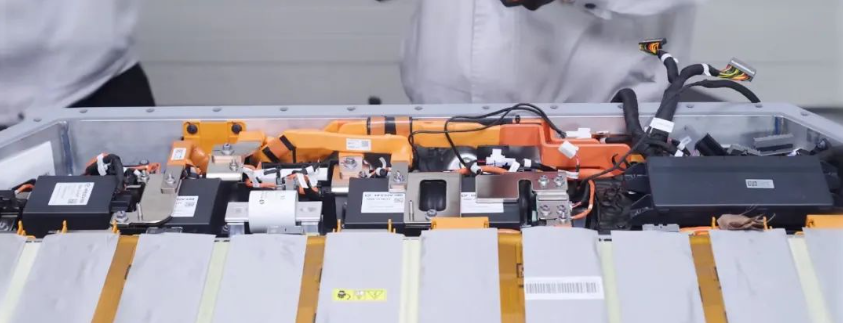
After opening the battery pack, you can see the electrical structure inside the battery pack. There are a total of six rows of battery cells, and the water cooling pipes are arranged on both sides of the battery pack. However, it is surprising to find that there are no horizontal beams in the battery pack. This is similar to Kirin There are differences when batteries are released. The high-voltage components are set at the front of the battery pack, separated from the battery by a beam in the middle, and the high-voltage part is cooled by a separate water-cooled plate.
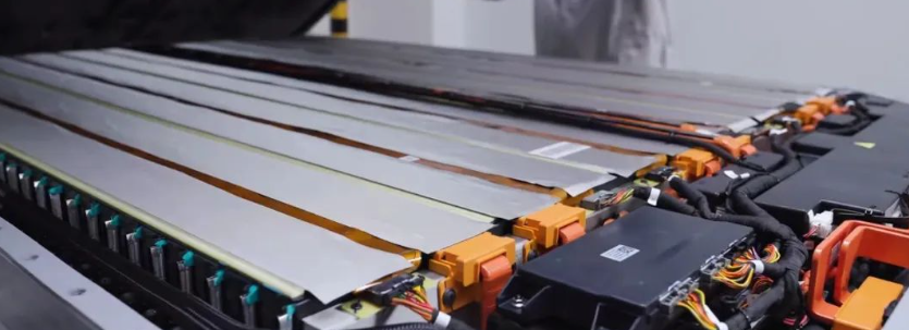
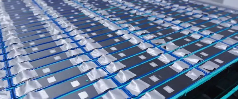
The battery cell is obviously placed upwards normally, and the CCS part is connected to the busbar by FPC+NTC plus nickel sheet welding, and the wire harness isolation plate is used, and the hot-pressed CCS is not used, which is also a bit interesting. The surface of the busbar is covered with a layer of thermal protection insulating material.
In addition, there is another detail that the top edge of each row of cells is reinforced with FR4 materials (yellow strips in the picture), which should be to increase the overall structural strength, and the top patch of the cell is short , did not cover the position where FR4 needs to be bonded.
3.Battery cooler for Qilin battery pack
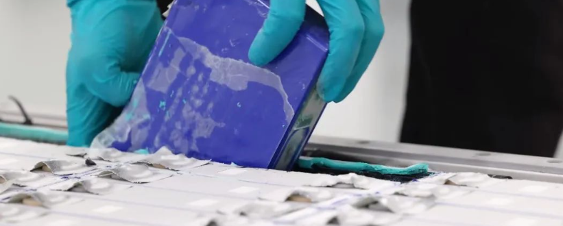
There is a water-cooled plate between the battery cell and the battery cell. There is no pressure relief valve on the top cover of the battery cell, and it can be seen from the bottom that it is set at the bottom. In addition, some foam-like materials are punched in the groove formed by the cell-cold plate-cell. It is estimated that this is to improve the cushioning capacity between the cells. It is guessed that this should be a foamed silicone pad. The double-sided adhesive should be used between the battery cell and the water-cooled plate, and the water-cooled plate itself should be powder-coated for insulation, which should be epoxy resin powder.
4.Qilin battery thermal runaway protection
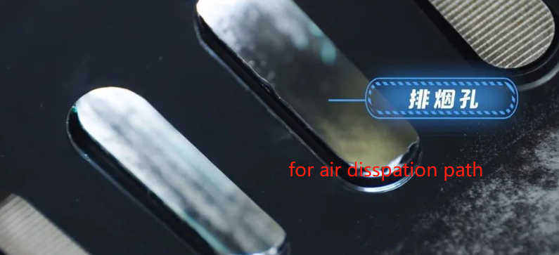
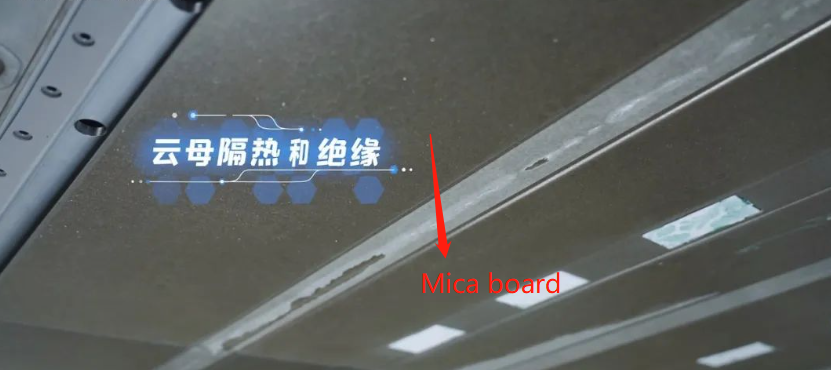
Further, it can be seen that the pressure relief valve of the battery cell is set at the bottom of the battery cell, and the bottom is not pasted with a PC top patch, mainly to allow the battery body on both sides of the bottom to be directly bonded to the structural adhesive to improve the structural strength. At the same time, the bottom is The structural glue is equipped with a glue blocking mechanism to prevent the structural glue from overflowing to the pressure relief valve. The shoulder-to-shoulder position of the battery cells is equipped with heat insulation materials to block the only channel for thermal runaway between the battery cells. A pressure relief and smoke exhaust hole is set at the position directly opposite the pressure relief valve, and a mica plate is arranged between the outer side of the lower case of the battery pack and the bottom guard plate for thermal runaway protection.
This is the first mass-produced version of the CATL Qilin battery. Ningde CATL will definitely further optimize and improve the design in the future, and there may be new surprises. BTW, qilin battery chemistry is Ternary lithium battery.
The cooling plate is an extruded cold plate with the same width as the cell width. There is something like cushioning foam between the battery cell and the cooling plate, which plays a role in absorbing tolerance and heat transfer. However, the battery cell is an 811 , and there is still a double about whether it can absorb the cell expansion at the end of its life.
Which is the mateirals htey used for the cooling challens? plastic cover? additionally, how is the integration of the battery cooling system done with the overall vehicle TMS? is the battery cirucits coupled with the A/C loop via a heat exhanger / chiller. Last, what about the battery pre-conditions – is it offered? thx for your support
Which is the mateirals htey used for the cooling challens? plastic cover? additionally, how is the integration of the battery cooling system done with the overall vehicle TMS? is the battery cirucits coupled with the A/C loop via a heat exhanger / chiller. Last, what about the battery pre-conditions – is it offered? thx for your support
The battery cooling plate material is stamped with AL3003 and then brazed into shape. There are flow channels on the stamped plate, and the flat plate is in contact with the module for cooling. The battery cold plate is coupled to the air conditioning refrigerant r134a through a chiller, and the other is coupled to the coolant. what is your meaning for battery pre-conditions? Does it refer to battery pre-cooling or pre-heating before fast charging? These can be pre-processed in advance through BMS strategy.